


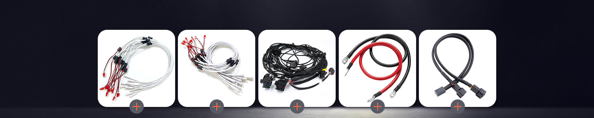
Why Choose Custom 8Pin JST and Molex PicoBlade Cable Assemblies for Compact Electronic Projects?
2026-11-18 10:17As electronic products become smaller, lighter, and more functionally integrated, engineers face increasing challenges when designing internal cable connections. Limited PCB space, narrow enclosure dimensions, multiple signal paths, and strict assembly requirements all make connector and cable selection more important.
For compact electronic projects, an 8pin JST connector cable or a Molex PicoBlade cable assembly can provide a practical wire-to-board connection solution when the connector series, pitch, wire specifications, and mechanical requirements are correctly matched.
However, selecting a connector based only on its pin count is not enough. An eight-position connector may still be unsuitable if its pitch, mating interface, current rating, or cable routing requirements do not match the PCB and product design.
This guide explains how hardware engineers and procurement teams can evaluate compact connector cable assemblies, compare key selection factors, and prepare a more accurate customization request.
1. Why Do Compact Electronic Projects Need Custom Cable Assemblies?
In compact electronic equipment, internal wiring is often restricted by limited installation space. Standard cables may have unsuitable lengths, connector orientations, wire gauges, or terminal configurations.
These mismatches can create several practical problems:
Limited installation space: Excess cable length can interfere with other components or make enclosure assembly difficult.
Connector compatibility issues: A connector with the correct number of positions may not match the PCB header or mating housing.
Unstable electrical connections: Poor terminal crimping, unsuitable contact specifications, or insufficient connector retention can lead to intermittent connections.
Difficult cable routing: Incorrect wire length or exit direction may increase bending stress and complicate assembly.
Inconsistent production: Manually cutting and terminating standard wires can introduce additional assembly steps and variation.
A custom electronic cable harness addresses these issues by matching the cable assembly to the actual electrical and mechanical requirements of the equipment.
For example, an eight-position cable assembly can be customized with a defined wire length, wire color sequence, connector configuration, terminal type, and branch arrangement. This helps reduce unnecessary wiring work during final product assembly.

2. How to Choose Between 8Pin JST and Molex PicoBlade Cable Assemblies
JST and Molex offer different connector families for compact electronic applications. The correct choice depends on the specific connector series rather than the brand name alone.
2.1 8Pin JST Connector Cable
JST provides multiple wire-to-board connector series with different pitches, current ratings, housing structures, and applicable wire ranges.
For example, the JST PH series uses a 2.0 mm pitch and is available in multiple circuit configurations, including eight-position versions. Its compact design makes it suitable for internal PCB connections in various electronic products.
When evaluating an 8pin JST connector cable, engineers should confirm:
Exact JST connector series and part numbers
Eight-position housing and mating header compatibility
Terminal model and applicable wire range
Connector orientation and cable exit direction
Rated current and voltage for the intended application
PCB mounting configuration and available installation space
The JST PH series is one possible reference when a 2.0 mm pitch connector is required. Its published specifications include an eight-position configuration, but the actual electrical and mechanical limits must be checked against the selected part and operating conditions.
2.2 Molex PicoBlade Cable Assembly
Molex PicoBlade is a compact wire-to-board connector family commonly associated with a 1.25 mm pitch.
Its small form factor makes it a candidate for electronic products where PCB space and connector dimensions are major design constraints.
A Molex PicoBlade cable assembly may be considered for applications such as:
Compact control boards
Small electronic modules
Consumer electronics
Embedded devices
Sensors and monitoring equipment
Battery-powered electronic products
Before ordering, buyers should verify the exact Molex series, circuit count, housing, mating header, terminal, and wire compatibility using the manufacturer's technical documentation.
2.3 Key Differences: JST PH and Molex PicoBlade
The following comparison uses the JST PH series as a representative JST example. It should not be interpreted as a comparison of every JST connector family against every Molex product.
| Selection factor | JST PH example | Molex PicoBlade |
|---|---|---|
| Typical pitch | 2.0 mm | 1.25 mm |
| Eight-position option | Available | Available in the relevant product family |
| Main design consideration | Balance of compact size and connection requirements | Smaller pitch for space-constrained designs |
| PCB compatibility | Requires matching PH header | Requires matching PicoBlade header |
| Wire compatibility | Depends on terminal and housing specifications | Depends on terminal and housing specifications |
| Selection priority | Electrical rating, dimensions, and mating compatibility | Space constraints, electrical rating, and mating compatibility |
Important: JST PH and Molex PicoBlade are not interchangeable simply because both are available in eight-position configurations. Their pitches and mating interfaces differ. Never force a connector into a non-matching header.

3. Technical Parameters to Confirm Before Customization
For hardware engineers and procurement teams, connector selection should be based on a complete set of electrical, mechanical, and manufacturing parameters.
3.1 Connector Pitch and Pin Configuration
Connector pitch is the center-to-center distance between adjacent contacts. It directly affects the PCB footprint and connector dimensions.
For an eight-position connector, the total contact-row span is determined by seven pitch intervals, not eight.
For example:
A 2.0 mm pitch connector has a nominal contact-row span of 14.0 mm.
A 1.25 mm pitch connector has a nominal contact-row span of 8.75 mm.
These figures describe the distance between the centers of the first and last contacts. They are not the overall housing dimensions.
Engineers should also confirm the following:
Pin numbering and viewing direction
Wire-to-board or wire-to-wire connection type
Header orientation: vertical or right-angle
Housing keying and polarization
Contact arrangement and mating direction
Providing the PCB connector part number or a clear drawing can significantly reduce compatibility risks.
3.2 Wire Gauge and Electrical Requirements
Wire gauge must be selected according to the current load, voltage drop, conductor material, cable length, insulation properties, and installation conditions.
For a low-current signal connection, a smaller wire may be suitable. Power-related circuits may require a different conductor size and terminal configuration.
Before specifying a cable assembly, provide:
AWG or conductor cross-sectional area
Number of conductors
Operating voltage
Normal and maximum current
Wire insulation material
Required temperature range
Cable length and acceptable voltage drop
Do not assume that every eight-position connector can carry the same current on all eight circuits simultaneously. The allowable current depends on the connector series, terminal, wire size, number of energized circuits, ambient temperature, and other derating conditions.
3.3 Cable Length, Routing, and Mechanical Design
The cable length should be determined from the actual installation path rather than the straight-line distance between two connection points.
For compact electronic products, engineers should consider:
Distance between the PCB and connected module
Available space inside the enclosure
Minimum recommended bending radius
Cable exit direction
Required slack for assembly and servicing
Potential contact with moving or heated components
If the cable passes through a narrow enclosure or around a corner, a customized cable length and routing arrangement can help simplify installation.
3.4 Anti-Vibration and Connection Reliability
Vibration can gradually affect electrical connections, particularly in equipment with moving parts or frequent handling.
A reliable cable assembly should consider more than the connector itself. Important factors include terminal retention, crimp quality, housing engagement, wire strain relief, and cable routing.
Recommended evaluation points include:
Terminal retention: Confirm that the terminal is correctly locked into the housing.
Crimp consistency: Check conductor crimping and insulation support against the terminal manufacturer's requirements.
Mating retention: Verify that the connector is fully engaged and that its locking structure is suitable for the application.
Cable strain relief: Avoid excessive pulling or bending forces at the connector exit.
Vibration validation: Define the actual test conditions and acceptance criteria when the application requires vibration testing.
A connector advertised as vibration-resistant does not automatically guarantee that the complete cable assembly will pass a particular vibration test. The complete assembly must be evaluated under the conditions relevant to the finished product.
4. Typical Applications of 8Pin JST and Molex PicoBlade Cable Assemblies
Compact multi-position cable assemblies are used in different electronic systems where several electrical connections must fit into a limited space.
4.1 Consumer Electronics
Small electronic products often require internal connections between the main PCB, display, control panel, sensor, and power module.
An eight-position cable assembly can organize multiple circuits into one compact connection, helping simplify product assembly and internal wiring management.
4.2 Industrial Control Modules
Compact control boards may need connections to sensors, switches, indicator modules, or communication interfaces.
A customized cable assembly can provide the required pin arrangement, wire identification, and installation length for the specific control system.
4.3 Smart Home and IoT Devices
IoT devices frequently combine wireless modules, sensors, power circuits, and control boards within compact enclosures.
The selection of a suitable connector pitch and cable configuration can help engineers balance PCB space, assembly convenience, and connection reliability.
4.4 Portable and Battery-Powered Equipment
Portable electronics often have limited internal space and strict weight requirements.
A compact connector cable can simplify connections between the battery management board, control PCB, display, and other internal modules. Current rating, insulation, temperature conditions, and battery-related safety requirements must be evaluated separately for each design.
5. What Should Buyers Check When Sourcing a Custom Electronic Cable Harness?
A successful purchasing decision requires more than comparing unit prices. Procurement teams should evaluate connector compatibility, manufacturing consistency, documentation, sample validation, and production communication.
The following checklist can help reduce unnecessary design changes and sourcing risks.
| Procurement item | Information to confirm | Why it matters |
|---|---|---|
| Connector brand and series | Exact JST or Molex part number | Prevents mating incompatibility |
| Pin configuration | 8 positions, pin numbering, wiring sequence | Avoids incorrect electrical connections |
| Connector pitch | 2.0 mm, 1.25 mm, or another specified pitch | Ensures PCB compatibility |
| Wire specification | AWG, conductor material, insulation | Supports electrical and mechanical requirements |
| Cable length | Overall length and tolerance | Ensures correct installation |
| Terminal crimping | Terminal model and crimp requirements | Supports stable electrical contact |
| Testing | Continuity, short-circuit, and other agreed tests | Helps verify assembly quality |
| Compliance documents | Applicable material declarations and test reports | Supports customer and market requirements |
| Sample approval | Appearance, dimensions, wiring sequence, and test results | Reduces mass-production risks |
5.1 RoHS Compliance and Material Documentation
For electronic products sold in markets with applicable hazardous-substance restrictions, material compliance should be considered during component sourcing.
RoHS requirements restrict specified hazardous substances in electrical and electronic equipment within the directive's scope. The limits generally apply to homogeneous materials rather than to the finished cable assembly as one undivided object.
When sourcing a custom electronic cable harness, buyers should clarify:
Whether the finished product or equipment falls within the applicable RoHS scope
Whether the connector, terminal, wire insulation, and other materials have relevant compliance documentation
Whether material declarations or third-party test reports are available
Whether the documents cover the actual components and material versions used in production
A supplier's general statement that a product is RoHS compliant is not a substitute for reviewing the relevant supporting documents. Buyers should also distinguish between a material declaration, a test report, and a complete product-level compliance assessment.
5.2 Sample Prototyping and Lead Time
Sample development is an important stage before mass production, especially when a project uses a customized eight-position connector cable.
The sample lead time depends on several factors:
Whether the connector and terminal parts are readily available
Whether the cable uses standard or customized wire specifications
Whether special crimping tools or fixtures are required
Whether drawings and wiring specifications are complete
Whether electrical or environmental validation is requested
A practical sample process usually includes:
Review the customer's drawing, sample, or connector part numbers.
Confirm the connector series, pin arrangement, wire specifications, and cable length.
Evaluate material and component availability.
Prepare the prototype cable assembly.
Check dimensions, wiring sequence, and agreed electrical characteristics.
Submit the sample for customer evaluation and approval.
Confirm the approved specification before mass production.
Instead of assuming a universal sample lead time, buyers should request a project-specific estimate after the technical requirements and material availability have been reviewed.
6. How Xiamen Evershine Supports Custom Cable Assembly Projects
For compact electronic projects, a suitable cable assembly must match the customer's electrical design and physical installation requirements.
Xiamen Evershine Electronic Technology Co., Ltd. specializes in the development, production, and sales of wires, cables, and wiring harness products.
For customers sourcing an 8pin JST connector cable, a Molex PicoBlade cable assembly, or another custom electronic cable harness, the project should begin with clear technical information.
The customization process can be organized around the following requirements:
Step 1: Technical Requirement Review
Customers can provide connector part numbers, PCB drawings, wiring diagrams, existing samples, or product specifications.
The key information includes connector series, circuit count, wire gauge, cable length, pinout, and application environment.
Step 2: Connector and Wire Configuration
The connector housing, terminals, and wire specifications should be checked for compatibility.
If the original connector is not fully identified, product photographs and dimensional information can help with preliminary evaluation. Exact part-number confirmation is still recommended before production.
Step 3: Prototype and Sample Confirmation
A prototype allows the customer to verify connector mating, cable routing, dimensions, and wiring sequence before moving forward.
Any requested electrical or mechanical tests should be agreed upon in advance, including the test method and acceptance criteria.
Step 4: Production and Quality Verification
After sample approval, the confirmed specification becomes the reference for production.
Depending on the agreed project requirements, verification may include wiring sequence checks, continuity testing, short-circuit testing, dimensional inspection, and visual inspection of terminal crimping and connector assembly.
Step 5: Delivery and Project Coordination
Production and delivery arrangements should be confirmed according to the approved configuration, material availability, order quantity, and delivery requirements.
By communicating technical details early, customers and suppliers can reduce avoidable specification changes and improve the efficiency of custom cable assembly sourcing.
7. How to Request a Quote for a Custom 8Pin JST or Molex PicoBlade Cable Assembly
To receive a more accurate quotation, hardware engineers and procurement teams should prepare the following information before contacting a cable assembly manufacturer.
Recommended RFQ information:
Connector brand and exact series or part number
Eight-position connector configuration
Required mating connector, if applicable
Connector pitch and mounting orientation
Wire gauge and insulation material
Wire color sequence and pinout diagram
Cable length and dimensional tolerance
Operating voltage and current
Application environment and temperature requirements
Required compliance documents
Sample quantity and estimated mass-production quantity
Target sample and production schedule
If a complete drawing is not available, customers can start with a physical sample, connector photographs, or a preliminary wiring diagram.
For Xiamen Evershine Electronic Technology Co., Ltd., these details provide a practical starting point for evaluating a custom cable assembly project and confirming the next steps.
Contact our team to discuss your 8pin JST connector cable, Molex PicoBlade cable assembly, or custom electronic cable harness requirements. Share your drawing, sample, or technical specifications to start a project evaluation.
Frequently Asked Questions
Q1: Are 8Pin JST and Molex PicoBlade connectors interchangeable?
No. The connector families use different dimensions and mating interfaces. For example, the JST PH series has a 2.0 mm pitch, while Molex PicoBlade uses a 1.25 mm pitch. The correct housing, terminal, and mating header must be selected from the same compatible connector family.
Q2: How do I choose between a 2.0 mm JST connector and a 1.25 mm PicoBlade connector?
Start with the PCB footprint, available enclosure space, electrical load, wire specifications, and mechanical retention requirements. A smaller pitch may help reduce connector space, but it does not automatically provide better electrical or mechanical performance.
Q3: Can an 8Pin JST cable assembly be customized with different wire lengths and colors?
Yes, a custom cable assembly can be specified with different wire lengths, colors, and wiring sequences, subject to connector and manufacturing compatibility. Provide a pinout diagram and dimensional requirements to avoid wiring errors.
Q4: How can I improve the vibration resistance of a compact cable assembly?
Check terminal retention, crimp quality, connector locking features, wire strain relief, and cable routing. If the finished product operates in a vibration environment, define the vibration profile and acceptance criteria for assembly-level validation.
Q5: What RoHS documents should I request from a cable assembly supplier?
Depending on the applicable regulatory scope and customer requirements, request relevant material declarations, component compliance information, and test reports. Confirm that the documents cover the actual connector, terminal, wire insulation, and other materials used in the supplied assembly.
Q6: How long does it take to receive a customized eight-pin cable sample?
There is no universal lead time. It depends on connector availability, wire specifications, tooling requirements, drawing completeness, and requested testing. Ask the supplier to confirm a sample schedule after reviewing the complete technical requirements.
Q7: What information is needed to quote a custom electronic cable harness?
At minimum, provide connector part numbers, pin configuration, wire gauge, cable length, wire colors, pinout, operating conditions, order quantity, and any required compliance or testing documents. Drawings or physical samples can help improve quotation accuracy.
Conclusion
Choosing the right compact connector cable assembly is a design decision that affects PCB layout, electrical performance, product assembly, and long-term connection reliability.
An 8pin JST connector cable may be appropriate when the selected JST series matches the available PCB footprint and electrical requirements. A Molex PicoBlade cable assembly can be considered when a 1.25 mm pitch interface is required for a more space-constrained design.
For both options, engineers should verify the exact connector series, mating compatibility, wire specifications, crimping requirements, vibration conditions, and applicable compliance documentation before approving production.
With clear drawings, samples, and technical specifications, Xiamen Evershine Electronic Technology Co., Ltd. can evaluate custom wire, cable, and wiring harness requirements and support customers through the project development process.