
What is an RF cable assembly?
2026-03-25 10:11With the widespread adoption of smart technologies, the application of cable accessories within the electronics and telecommunications industries has become increasingly extensive. But what exactly constitutes an RF cable assembly? This is a common question—and often the biggest point of confusion—for those new to the cable field. Below, we present a breakdown of key concepts to help everyone learn and understand this topic together.
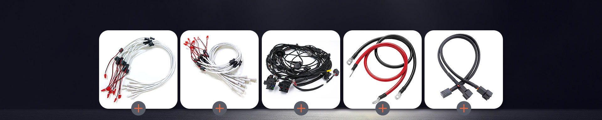
I. What Is a Cable Assembly?
Cable assemblies primarily encompass wires, magnet wires, insulated wires for motors and electrical appliances, power cables, communication cables, and optical cables. Broadly speaking, a "cable assembly" refers to materials utilized for power transmission, communication, and related data transfer purposes. There is no strict, rigid boundary distinguishing "wires" from "cables." Typically, products with fewer cores, smaller diameters, and simpler structures are referred to as "wires"; specifically, uninsulated conductors are designated as "wires," while all others are classified as "cables." Furthermore, conductors with a larger cross-sectional area (greater than 6 square millimeters) are termed "large wires," while those with a smaller area (less than or equal to 6 square millimeters) are termed "small wires"; insulated wires are also frequently referred to as "building wires" (or wiring cables). Cable categories include power cables, control cables, compensation cables, shielded cables, high-temperature cables, computer cables, signal cables, coaxial cables, fire-resistant cables, marine cables, and many others. All of these are composed of multiple strands of conductive wire and serve to interconnect electrical circuits, appliances, and various other devices.
II. What is a Cable Assembly?
A cable assembly is an electrical interconnection component used to link various electronic systems or subsystems; it consists of various types of insulated wires, shielded cables, and electrical connectors. With the widespread application of cable assemblies in the telecommunications sector, requirements regarding their electrical performance stability, service life, and environmental resistance have become increasingly stringent. Currently, most commonly used cable assemblies feature connectors at both ends with a cable section in between; the cable and connectors are joined via crimping, mechanical assembly, or soldering, and are subsequently protected by heat-shrink tubing or injection molding.
III. Primary Classifications of RF Coaxial Cables
Currently, the company's existing RF coaxial cable portfolio is categorized by the following 14 application characteristics: CLA Series (Low-Loss, Phase-Stable), CLB Series (Ultra-Low-Loss, Phase-Stable), CLC Series (Solid PTFE Internal Interconnect Cables), CLD Series (Economical Low-Loss, Phase-Stable Cables), CLE Series (Solid LDPTFE Low-Loss, Phase-Stable Cables), CLF Series (Low-Loss, Phase-Stable Cables), CLS Series (Ultra-Flexible, Low-Loss, Phase-Stable Cables), CLG Series (Ultrabend Cables), CR Series (Semi-Flexible Cables), CB Series (Semi-Rigid Cables), RG Series (Military-Standard Cables), CMR Series (Low-Loss Cables), CT Series (Test Cable Assemblies), and CVNA Series (Test Cable Assemblies). Supported operating frequencies include: 6 GHz, 8–9 GHz, 18 GHz, 26.5 GHz, 40 GHz, 50 GHz, and 67 GHz.

Different types of cables should be selected for different application scenarios. Semi-rigid and semi-flexible cables are typically used for internal equipment interconnections, whereas flexible cables are recommended for test and measurement applications. A cable assembly consists of an RF cable fitted with connectors specifically designed for RF coaxial cables.
Please feel free to call us anytime if you have any questions!
IV. Key Parameters in RF Cable Testing
Assessing the quality of a test cable is paramount for testing applications; ensuring consistent, repeatable test results and maintaining reliable electrical performance over the long term are particularly critical. To this end, cable assemblies must be durable enough to withstand frequent movement, bending, and exposure to various environmental conditions while simultaneously preserving their reliable electrical characteristics.
1. Electrical Performance Metrics
Electrical performance metrics are the primary considerations. Generally, the higher the operating frequency, the more stringent the requirements for the cable's performance specifications. The key metrics include the following:
① Voltage Standing Wave Ratio (VSWR): The closer the VSWR is to 1, the better the performance; a higher return loss corresponds to higher accuracy in the test system. VSWR Stability: Whether the test cable's VSWR curve remains stable—without drifting—during movement or bending directly determines the consistency of the Device Under Test (DUT) performance.
② Phase Stability vs. Flexure and Amplitude Stability vs. Flexure: These metrics primarily refer to the changes in the cable assembly's electrical length and insertion loss when subjected to specified mechanical bending or twisting conditions.
③ Insertion Loss: The insertion loss of a test cable can be calibrated out at the Vector Network Analyzer (VNA) port; therefore, it is not a critical factor directly affecting the testing process itself. A test cable's insertion loss is primarily composed of three components: connector loss, cable loss, and loss resulting from impedance mismatch.
2. Mechanical and Physical Properties
Proper handling techniques can significantly extend the service life of a test cable. During use, appropriate protective measures should be taken; please make every effort to avoid cutting, scratching, or damaging the cable through excessive bending.
Key mechanical and physical metrics include:
① Flexibility: Test cables are subject to relatively high requirements regarding flexibility. Flexibility is not determined solely by the jacket material; rather, variations in the structural composition—from the inner conductor, dielectric layer, and outer conductor to the jacket material—all influence the cable's overall flexibility.
② Retention Force (Longitudinal Tensile Strength): During use, test cables are frequently subjected to pulling and twisting forces. Common issues—such as cable breakage or separation at the cable-to-connector junction—are often the result of improper handling. Furthermore, test cables exhibiting superior retention force typically feature high-quality materials in their braided shielding layers and optimized structural designs in their connectors.
③ Flex Cycle Life: The number of bending cycles a cable can withstand before failure is directly correlated with the quality of its structural design and constituent materials. If a cable lacks sufficient flexibility for repeated bending, it is prone to central conductor breakage and deformation of the braided shielding.
V. Regulatory Requirements and Specialized Equipment
Certain applications—such as those in the military, government, avionics, aerospace, and industrial equipment sectors—are subject to specific regulations and impose distinct requirements regarding coaxial cable performance. A cable can be qualified for use in these fields only if it satisfies the pertinent regulatory requirements established by industry bodies, societal standards, and government agencies. These requirements can be quite complex and challenging to memorize; consequently, experts often serve as the best resource for navigating the intricacies of these details.
VI. Factors to Consider When Selecting RF Cable Assemblies
When selecting RF cable assemblies, it is essential to take a comprehensive approach that considers various factors.
① Identify the location of the open-circuit point within the cable's time-domain characteristic curve. Operationally, this involves connecting the cable assembly—which has already had a connector installed at one end—to the test port of a network analyzer.
② Subsequent data calculations and analyses are based on the phase data obtained at this specific frequency, with the ultimate goal of achieving phase alignment. Consistency in length or phase is achieved by mechanically trimming the physical length of the cable; the feasibility of this process depends on the uniformity of the cable's dielectric material and the length tolerance range of the associated phase-matching components. Furthermore, the phase-trimming step can be executed using methods that do not require detaching the connector or physically cutting the cable.
③ The reserved cable length does not necessarily have to be exactly one wavelength. After undergoing the assembly procedures outlined in the first and second steps above, the phase angles of the cable assemblies typically fall within a relatively narrow distribution range.